![]()
Factory direct sales - solid capacitor - patch aluminum electrolysis, to ensure that the factory first-class goods!
1. Division of processes
Compared with the machining of ordinary machine tools, the machining process is more concentrated. According to the processing characteristics of CNC machine tools, the machining process is divided into the following ways:
1) According to the clamping positioning process
This method is generally suitable for processing workpieces with few contents, mainly by dividing the processing part into several parts, and processing each part in each process. For example, when machining the shape, it is clamped in the inner cavity; when the inner cavity is machined, it is clamped in the shape.
2) According to the tool division process
In order to reduce the number of tool changes and the time of the lost time, the principle of dividing the tool can be used to divide the process. In one setup, all the machining parts that can be processed are completed with one knife, and then the second knife is replaced to process other parts. This method is mostly used in special CNC machine tools or machining centers.
3) Dividing the process by roughing and finishing
For parts that are prone to machining deformation, taking into account the machining accuracy and deformation of the workpiece, the process can be divided according to the principle of coarse and fine machining, that is, coarse and fine.
In the division of the process, it is necessary to be flexible according to the structural requirements of the workpiece, the way the workpiece is mounted, the processing technology of the workpiece, the performance of the CNC machine tool, and the organization and management of the factory.
2. Arrangement of processing sequence
The arrangement of the processing sequence should be based on the structure of the workpiece and the condition of the blank, and the positioning and installation of the workpiece should be selected. The key point is to ensure that the rigidity of the workpiece is not damaged and the deformation is minimized. Therefore, the processing sequence should follow the following principles:
1) The processing of the previous process cannot affect the positioning and clamping of the next process
2) Machining the outer contour of the workpiece after machining the inner cavity of the workpiece
3) Minimize the number of repeated positioning and tool change
4) In the multi-pass process of one installation and processing, the process of less rigid damage to the workpiece is arranged first.
3. The connection between CNC machining process and common process
Since the numerical control machining process is interspersed in the whole process of workpiece machining, each process needs to establish state requirements for each other, such as the reserve of machining allowance, the accuracy of positioning surface and hole and the tolerance of shape and position, and the technical requirements of the orthopedic process. For the heat treatment of the blank, etc., each process must be considered before and after consideration.
4. Design of CNC machine tool processing and processing route
The main tasks of CNC machine tool processing design: determine the specific processing content, cutting amount, process equipment, positioning and installation method and tool movement track of the process, and prepare for the programming. The setting of the machining route is a very important link. The machining route is the movement track of the tool point relative to the workpiece during the cutting process. It not only includes the content of the machining process, but also reflects the arrangement of the machining sequence. Therefore, the machining route is An important basis for writing machining programs.
1) Principles for determining the processing route
1 The processing route should ensure the accuracy and surface roughness of the workpiece to be machined.
2 Design the processing route to reduce the idle travel time and improve the processing efficiency.
3 Simplify the numerical calculation and reduce the program segment, reducing the programming workload.
4 According to the shape of the workpiece, the stiffness, the machining allowance, the rigidity of the machine tool system, etc., the number of cycle machining is determined.
5 Reasonable design of the cutting and cutting direction of the tool. The unidirectional approach positioning method is adopted to avoid the positioning error caused by the backlash of the transmission system.
6 Reasonable selection of milling or up-cut milling in milling. Generally speaking, CNC machine tools use ball screws with small movement clearance, so the advantage of down-cut milling is more than that of up-cut milling.
2) CNC machine tool processing route
1 CNC lathe processing route
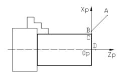
The machining path of the turning surface of CNC lathe is shown as AB-0p-D in Figure 1, where A is the tool change point, B is the cut point, C-0p is the tool cutting path, 0p is the cutting point, and D is the retract point.

Figure 1 CNC lathe turning end face machining route
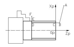
The machining route of the CNC lathe turning outer circle is shown as ABCDEF, where A is the tool change point, B is the cutting point, CDE is the tool cutting path, E is the cutting point, and F is the retracting point.

Figure 2 CNC lathe turning external machining route
2 CNC milling machine processing route
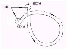
When the side cutter of the end mill mills the outer contour of the plane part, it avoids the normal cutting and cutting along the outer contour of the part. As shown in Figure 3, it should be cut or cut along the tangential extension of the outer contour curve. The cutting edge cuts produced when cutting in or cutting out ensure a smooth transition of the part surface. When milling the inner contour surface, the tool also enters and retracts along the tangential direction of the contour line. As shown in Fig. 4, ABC is the tangential cutting path of the tool, CDC is the closed contour of the tool cutting workpiece, CEA Cut the contour path for the tool tangentially.

Figure 3 Processing route for outer contour milling

Figure 4 The machining route for contour milling
3-hole machining positioning route
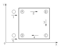
Reasonable arrangement of the hole machining positioning route can improve the positional accuracy of the hole. As shown in Fig. 5, the four holes A, B, C, and D are processed in the XY plane, and the alignment direction of each hole must be paid attention to when arranging the hole processing route. That is, the unidirectional approach positioning method is adopted, after the C hole processing is completed, the distance is moved to the left for a certain distance, and then the processing is returned to the D hole. This positioning method avoids the positioning error caused by the backlash of the transmission system, and improves the D hole and other Positional accuracy between holes.

Figure 5 hole machining positioning route
5. Workpiece installation and fixture selection
1) Mounting of the workpiece
1 Strive to meet the benchmarking principle of design basis, process reference, installation reference and workpiece coordinate system.
2 Reduce the number of clamping times, as far as possible to process all the surfaces to be processed after one clamping.
3 Use special fixtures as much as possible to reduce the time required for clamping and adjustment.
2) Selection of fixtures
According to the processing characteristics of the CNC machine tool, coordinate the relationship between the fixture coordinate system, the machine coordinate system and the workpiece coordinate system, in addition to the following points:
1 Small batch processing of parts, try to use combination fixtures, adjustable fixtures and other general fixtures.
2 batch production considers the use of special fixtures, and strives to facilitate loading and unloading.
3 The positioning of the clamp and the clamping mechanism components cannot affect the tool movement of the tool.
4 Handling and unloading parts should be convenient and reliable. Pneumatic clamps, hydraulic clamps and multi-station clamps can be used for batch production.


